
CT Iron: How Iron-Core Current Transformers Work
Understand the role of magnetic iron cores in electrical current measurement, including their construction, applications, performance limitations, and safety requirements.

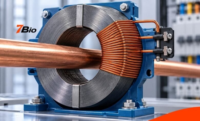
CT iron is a term sometimes used to refer to the magnetic iron core inside a current transformer (CT). This electrical device measures alternating current without directing the full primary current through a conventional measuring instrument. The more precise engineering terms are iron-core current transformer and current transformer core.
These components are found in electricity meters, industrial monitoring equipment, distribution systems, and electrical protection arrangements. Their construction influences how accurately current is measured and how reliably a protective device receives information during abnormal operating conditions.
Understanding the magnetic core is particularly useful for anyone learning about electrical equipment, evaluating current sensors, or reading technical specifications.
What Is CT Iron?
In electrical engineering, CT stands for current transformer. In this context, the iron refers to the ferromagnetic material used to form its magnetic core, although modern designs may use electrical steel, ferrite, or other specialized magnetic materials.
A current transformer converts a comparatively large alternating current into a smaller proportional signal that suitable instruments can measure.
For example, a transformer rated 100/5 A is designed to produce a nominal secondary current of 5 amperes when its primary current reaches 100 amperes, subject to its specified operating conditions.
The device does not remove current from the main conductor. Instead, it uses electromagnetic induction to reproduce a measurable representation of that current in a separate secondary circuit.
CT iron is not an official universal classification, chemical element, or single product brand.
How Does an Iron-Core Current Transformer Work?
A conventional current transformer works on electromagnetic induction.
When alternating current flows through an electrical conductor, it generates a changing magnetic field. A magnetic core surrounding the conductor provides a path for magnetic flux to circulate.
A secondary winding, usually many turns of insulated copper wire, wraps around the core.
The changing magnetic flux links with this winding and induces an electrical response; when the secondary circuit is correctly connected to its intended load, a secondary current flows.
The winding ratio largely determines the relationship between primary and secondary current, although real transformers have losses and measurement errors.
Consider an illustrative 100/5 A current transformer. If it operates ideally with 60 A flowing through its primary conductor, the secondary current would be approximately 3 A.
Actual measurements depend on the transformer’s accuracy, connected burden, and operating conditions.
The core makes this process practical by efficiently concentrating and guiding magnetic flux between the primary and secondary circuits.
Why Is the Magnetic Iron Core Important?
The magnetic core is central to the accuracy and behavior of many conventional current transformers.
Without an appropriately designed magnetic path, the transformer may require more excitation current or fail to reproduce the primary current with the intended accuracy.
Three properties are particularly relevant.
Magnetic permeability: A material with suitable permeability can establish magnetic flux effectively in response to a magnetizing field.
Core losses: Energy is dissipated through mechanisms including hysteresis and eddy currents. Core materials and construction methods are selected partly to control these losses.
Saturation characteristics: Every practical ferromagnetic core has limits. When magnetic flux approaches the material’s saturation region, transformer performance becomes increasingly nonlinear.
Therefore, a suitable material is not selected simply because it contains iron. Its magnetic characteristics must match the transformer’s measurement or protection requirements.
What Materials Are Used in CT Iron Cores?
Many conventional transformers use specialized electrical steel rather than ordinary structural iron.
One established option is cold-rolled grain-oriented electrical steel, commonly abbreviated as CRGO.
This iron-silicon alloy is manufactured to provide useful magnetic properties, including high permeability and relatively low core losses.
Manufacturers may assemble or wind thin layers of electrical steel to create the magnetic structure.
The layered construction limits circulating eddy currents that would otherwise cause unwanted heating and energy losses.
Other current-sensing designs use ferrite or specialized magnetic alloys. The appropriate choice depends on factors such as frequency, available space, current range, accuracy and cost.
Although these materials perform related functions, their magnetic properties differ.
Therefore, the term iron core should not be interpreted as a guarantee that every current transformer uses the same material.
Main Types of Iron-Core Current Transformers
Current transformers come in several constructions, each suited to specific electrical applications.
T
| Type | Construction | Typical consideration |
|---|---|---|
| Solid-core CT | Continuous magnetic ring | Suitable for installations where the conductor can be passed through the opening |
| Split-core CT | Magnetic core opens into sections | Can fit around an existing conductor without disconnecting it, subject to electrical safety procedures |
| Wound-primary CT | Has a dedicated primary winding | Used where the required ratio or construction calls for a wound primary |
| Bar-type CT | Uses a bar conductor as its primary | Common in certain switchgear and power-distribution arrangements |
The construction alone does not establish accuracy.
Two transformers with similar external appearances may have different current ratios, output signals, insulation requirements, and accuracy ratings.
Their datasheets must be consulted before selection.
Where Are Iron-Core Current Transformers Used?
Current transformers perform several distinct functions in electrical systems.
Electricity metering: They let meters measure larger currents indirectly. This is particularly useful in commercial and industrial electrical installations.
Energy monitoring: Sensors can provide current measurements to monitoring equipment, helping track electrical loads and energy use.
Protection systems: Suitable protection-class current transformers supply signals to relays that detect abnormal current conditions, including certain electrical faults.
Industrial control: Current measurements can support equipment supervision, load monitoring, and control-system diagnostics.
Power distribution: Current transformers are used in switchgear, substations and other parts of electrical distribution infrastructure.
Although the underlying induction principle is similar, applications have different performance requirements.
A transformer selected for routine energy measurement is not automatically suitable for protective relaying.
Metering CTs and Protection CTs: What Is the Difference?
Metering and protection transformers are designed around different operating priorities.
A metering transformer is typically expected to provide accurate measurements within a specified normal operating range.
A protection transformer must provide an appropriate representation of current under the abnormal conditions relevant to its protective function.
During a major electrical fault, current can rise far above ordinary operating values. The magnetic core must be designed to meet the protection scheme’s requirements.
For this reason, protection CT specifications often include information about their accuracy limit, rated burden, and saturation performance.
Some installations use separate cores or windings for metering and protection.
Selection must be based on the applicable equipment specifications and protection-system design, not the assumption that a higher current rating is always better.
What Is CT Core Saturation?
Core saturation occurs when increasing the magnetizing force no longer produces a proportionate increase in magnetic flux.
As a current transformer approaches saturation, its secondary signal may become distorted or stop following the expected relationship with the primary current.
This can introduce serious measurement errors.
In protection applications, excessive saturation may prevent a relay from accurately representing the fault current.
Several factors can affect saturation behavior, including:
- Magnetic core material and dimensions
- Primary current magnitude and waveform
- Secondary circuit burden
- Residual magnetism in the core
- Transient conditions during electrical faults
A current transformer’s suitability cannot be established from its nominal current ratio alone.
For demanding applications, qualified engineers must evaluate the complete protection or measurement arrangement.
How to Choose the Right Current Transformer
A suitable transformer must be matched to the equipment and electrical system in which it will operate.
The following specifications deserve particular attention.
| Specification | Why it matters |
|---|---|
| Primary current rating | Determines the intended current range |
| Secondary output | Must match the connected meter or monitoring device |
| Accuracy class | Indicates specified measurement performance |
| Rated burden | Describes the permitted secondary loading under rated conditions |
| Core construction | Influences physical installation requirements |
| Frequency rating | Must match the intended AC system |
| Insulation rating | Must be appropriate for the installation environment |
| Protection characteristics | Relevant where a transformer supplies protective equipment |
The secondary output requires special care. Some CTs provide a standard current output, such as 1 A or 5 A at rated primary current. At the same time, some monitoring sensors include an internal burden resistor to provide a voltage output.
These arrangements are not universally interchangeable.
The connected instrument must be compatible with the particular CT model.
Important Electrical Safety Risks
Current transformers are often installed close to conductors carrying dangerous electrical voltages.
One particularly serious hazard concerns opening the secondary circuit of a conventional current-output CT while primary current continues to flow.
Under these conditions, the transformer can develop dangerously high secondary voltage.
The exact behavior depends on its design, but the potential consequences include insulation failure, equipment damage and electric shock.
Some voltage-output CT sensors have internal burden resistors or protective arrangements that change this behavior. Their safety characteristics must be confirmed by the manufacturer.
Only appropriately qualified personnel should install and maintain CTs, following the equipment manufacturer’s instructions and applicable electrical safety procedures.
A split-core design does not make an electrical cabinet safe to open or work inside.
Common CT Measurement Problems
Incorrect readings do not always indicate a defective transformer.
One possible issue is reversed orientation or secondary polarity, which can affect directional power measurements.
Another is an incorrect transformer ratio entered into the monitoring system. A meter configured with the wrong CT ratio may display values that do not accurately represent the actual current.
A third problem is unsuitable secondary loading. The resistance of connecting leads and the connected instrument’s requirements can affect measurement accuracy.
Core saturation is another potential error source, particularly when current exceeds the transformer’s intended performance range.
Physical core damage, an incompletely closed split core, or deteriorating connections can also affect operation.
Troubleshooting must follow the manufacturer’s approved procedures. Readers should not disconnect CT wiring or examine energized electrical compartments to investigate readings themselves.
How Is an Iron-Core CT Different From a Rogowski Coil?
A conventional iron-core transformer uses a ferromagnetic core to couple the magnetic field to its secondary winding.
A Rogowski coil uses a different sensing arrangement without a ferromagnetic core. Its output relates to the rate of change of the measured current and usually requires signal processing or integration.
The absence of an iron core avoids conventional ferromagnetic saturation, but it also introduces different signal-processing and system-design requirements.
Neither technology is universally superior.
The right choice depends on the current range, required accuracy, available space, transient behavior, connected electronics, and intended application.
FAQs
1. Is CT iron the same as ordinary cast iron?
No. Current transformer magnetic cores commonly use engineered electrical steel or other specialized magnetic materials. Ordinary cast iron does not provide the same specified magnetic performance.
2. Can an iron-core current transformer measure direct current?
A conventional induction-based current transformer cannot measure steady direct current because it relies on changing magnetic flux. Other sensor technologies can measure DC.
3. What does a 100/5 A CT rating mean?
It indicates a nominal primary-to-secondary current relationship of 100 A to 5 A. Actual accuracy depends on the transformer’s specifications and operating conditions.
4. Why do CT magnetic cores use thin steel layers?
Laminated or wound electrical-steel construction helps reduce eddy-current losses, improving the magnetic core’s operating characteristics.
5. Can a current transformer become inaccurate over time?
Yes. Damage, improper loading, connection issues, or operation outside specified limits can degrade measurement quality. However, age alone does not establish that a transformer is inaccurate.
Final Takeaway
CT iron is best understood as a reference to the magnetic core used in an iron-core current transformer, rather than as a separate, formally defined electrical technology.
The core plays a major role in electromagnetic induction, measurement accuracy, and saturation behavior. Its material, design and magnetic performance help determine whether a transformer is suitable for metering, monitoring or electrical protection.
Anyone selecting or specifying this equipment should consult manufacturer documentation, verify compatibility, and ensure that qualified professionals handle electrical installation and maintenance